GHD S7N261 Gold & S7N421 Max Complete Guide
These two models have been available for some years now and are current GHD models.
We have taken a series of images to show you how these models come apart without damaging them and we also describe the parts the average DIYer can replace.
Generally we would suggest using our fixed price repair service HERE.
That way you are guaranteed to receive a succesful repair using the correct parts.
Indication of a fault is usually a flashing red LED and a squeal sound. This repeats and may be intermittant.
Parts you can expect to change yourself are:
- The mains cable
- Plastic casings
- Ceramic plates
Parts you can not change yourself are:
- Elements
- Thermal fuses
- PCB
Why is this model hard to repair?
Newer models of GHD no longer use the old tried and tested way of controlling the temperature with a surface mounted thermistor.
Instead, they decided to use a PRT embedded inside each element during manufacturing.
Why is this a problem for the repairer?
Each PRT has a slightly different value, from around 450 ohms to around 650 ohms.
This means that careful adjust of values stored in a processor "brain" memory on the PCB has to made in the factory so each element attains the correct temperature.
This requires specialist equipment, software and the knowledge of how to use them.
We have the equipment and software required to make these changes when we have to fit a replacement element.
This is the reason we do not sell elements and PCB's to the customer.
Now I hear you saying "but I have seen elements being sold on eBay for these models"
And you are correct, other "repairers" think it is OK to sell you elements that you can not match to the settings stored in your PCB and sell you totally unsuitable thermal fuses as well.
Lets say both of your elements measure 500 ohms on a pleasant day that's around 21 degC
If you purchase an element from a seller, the chances of getting one the same or close to the value you need for the calibration values stored on your PCB is extremely low.
Does it matter? Yes! Because the temperature of the replacement element will be wrong, it will be too low or too high. And I have seen other repairers work and DIY bodges that have led to temperatures of over 215 degs C.
These models should run at 185 degC which is the glass transition temperature of human hair.
So now your irons are ineffectively low in temperature or dangerously high!
Why do Heater Elements crack in this model?
If an element is cracked it is usually on the non switch side of the irons and this is not a random fault, nor have the irons been dropped to cause this.
Here's my thoughts.
During Covid many things became scarce including electronic components. I believe that substitute parts were used in a section of the circuit board that were possibly not quite suited to the job.
This has caused instant, uncontrolled heating and either thermal fuse failure or cracking of the element on the non switch side arm.
I see this fault dozens of time a week.
So, is there a solution?
Yes, there is. we change four components on the circuit board on every single pair that come in to us to avoid this failure happening in future
This requires specialist soldering equipment and a microscope.
We then fit a replacement element and carefully adjust the values stored in the PCB to attain the correct temperature.
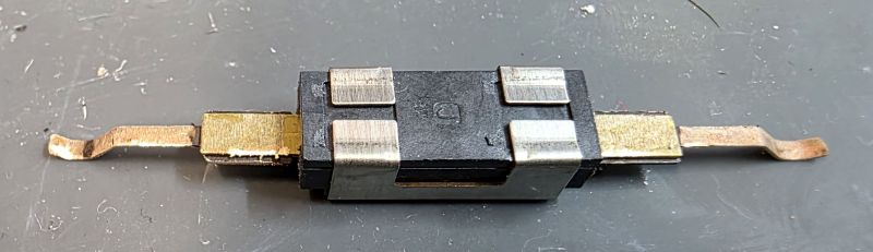
Thermal fuse failure
Both elements have a PEPI H1 thermal fuse fitted. These will go open circuit in the event of uncontrolled heating to avoid melting or a fire.
These can fail and can be replaced with genuine PEPI H1 thermal fuses.
But, the modifications, mentioned earlier, to the PCB must be carried out or the replacement thermal fuse will likely fail again or the non switch side element will crack.
Some "repairers" have taken it upon themselves to offer unsuitable thermal fuses as replacements. That is a very bad idea. The designers of these products, GHD in Cambridge, decided on the thermal fuse and various approvals of the design would be in place along with rigorous testing procedures.
If you fit or sell the wrong type of thermal fuse you will be liable if anything goes wrong in the future!
For £39.99 is it worth the risk and trouble to yourselves? Please use a repair service where the parts used are correct, like ours HERE
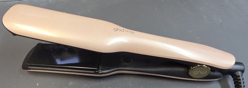
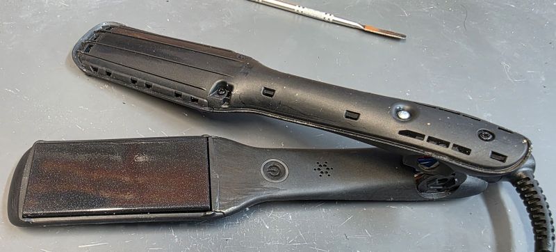
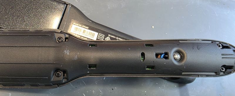
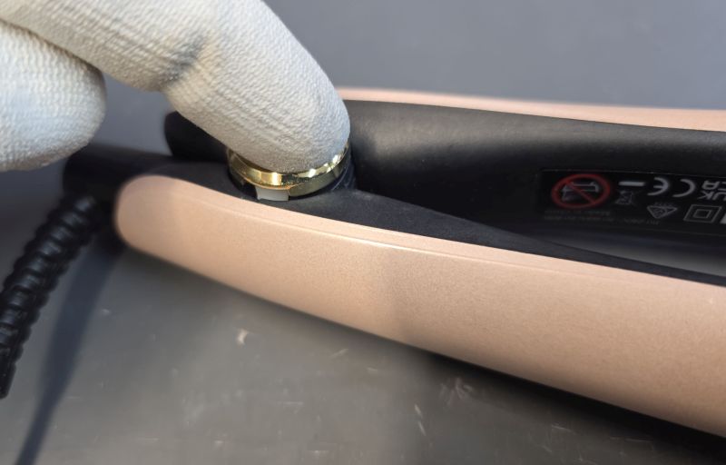
How to take apart the S7N421 Max
The method is exactly the same for the S7N261 Gold.
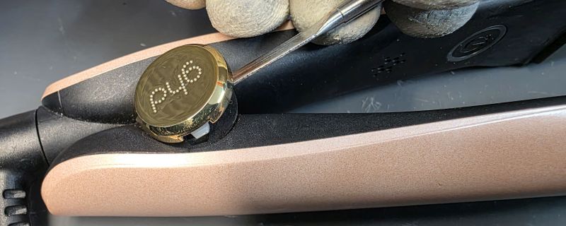
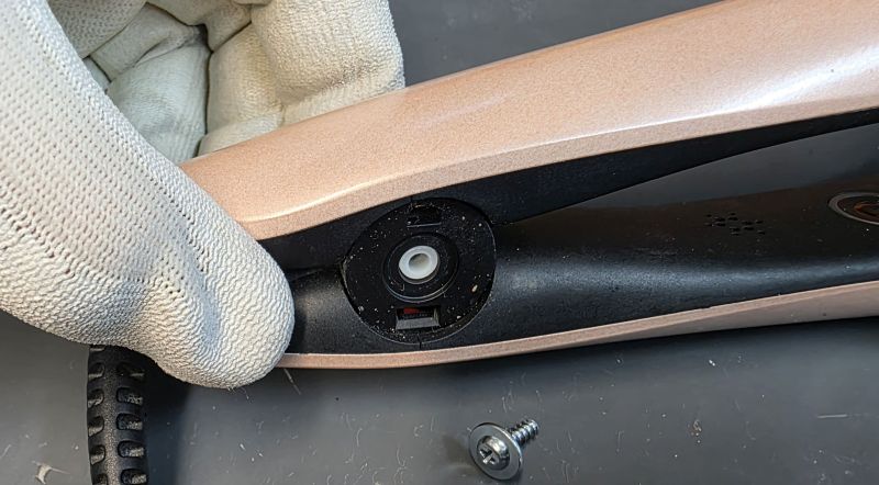
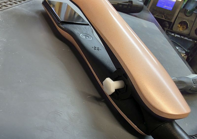
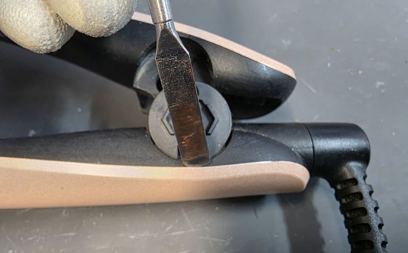
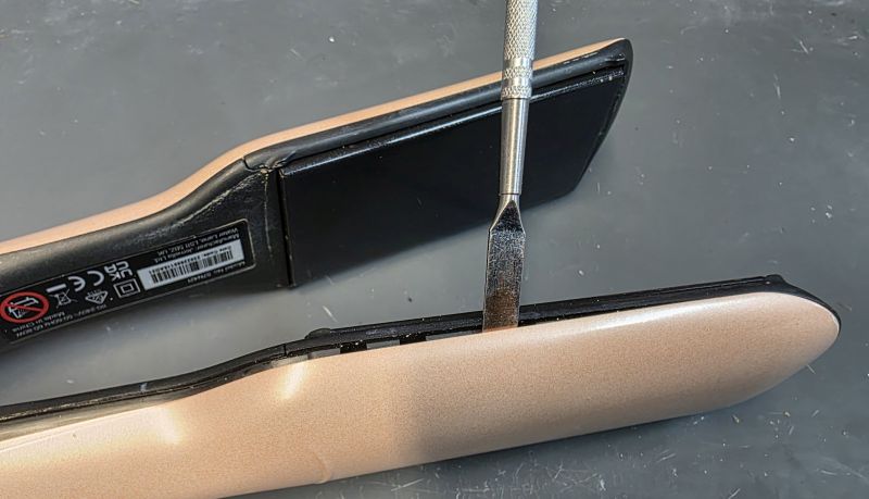
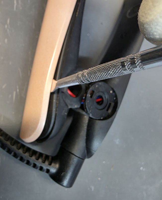
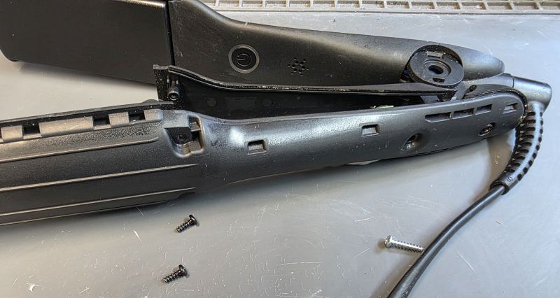
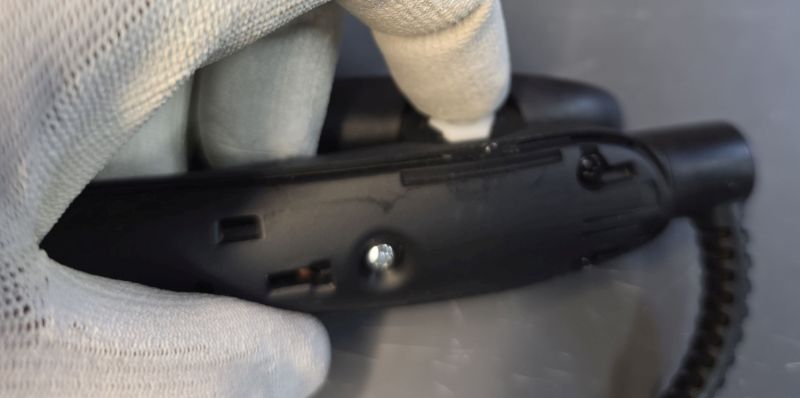
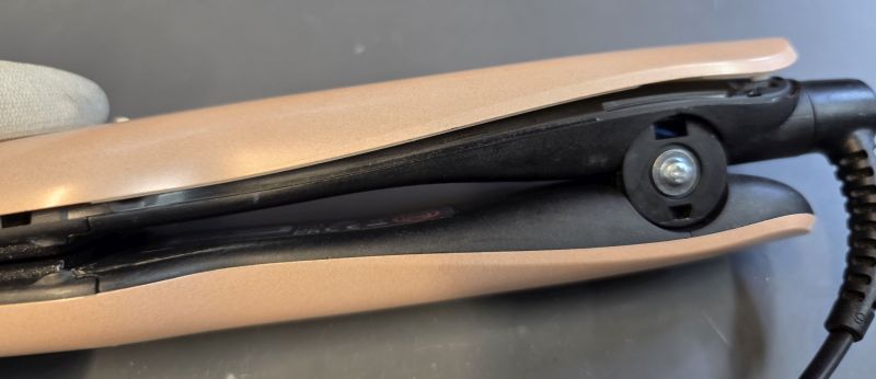
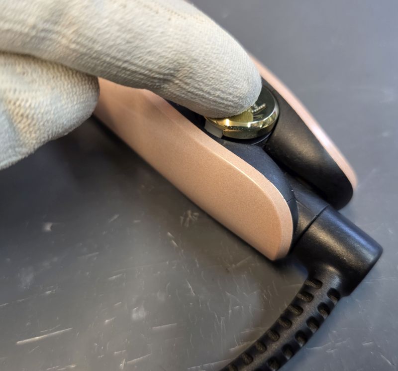
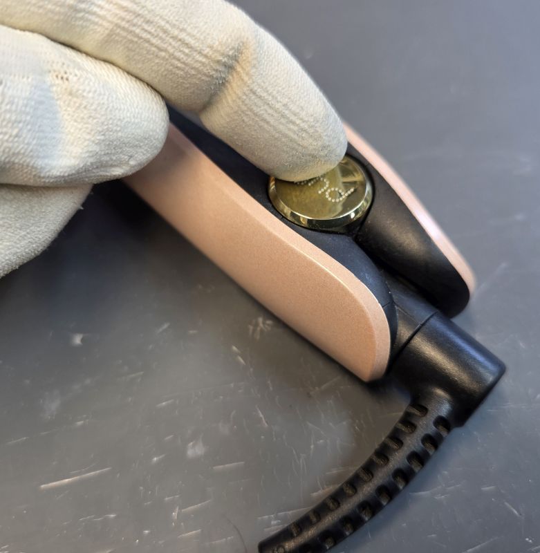
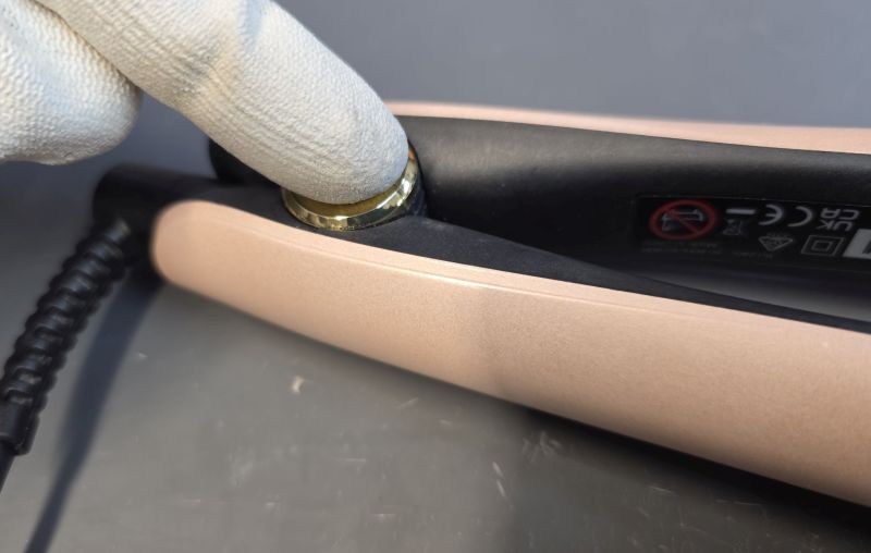
Remove Hinge Covers
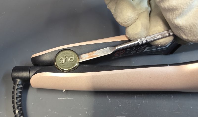
A small flat blade slides under the hinge cap.
Gently prise the cap off.
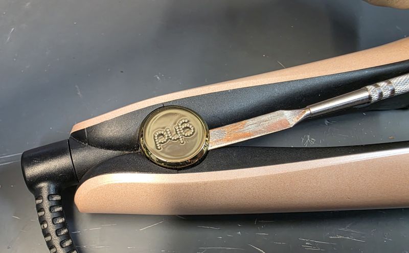
Repeat on the opposite side.
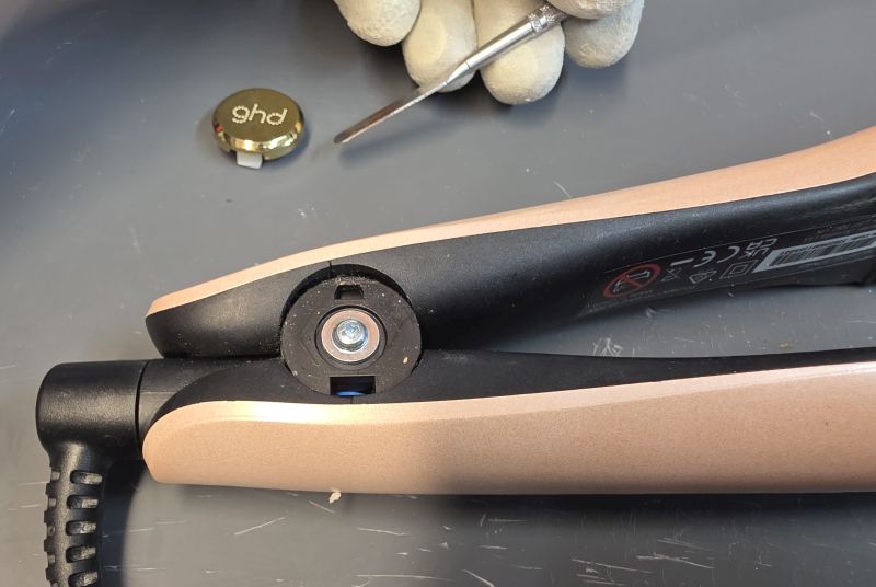
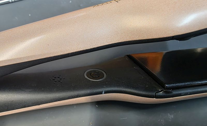
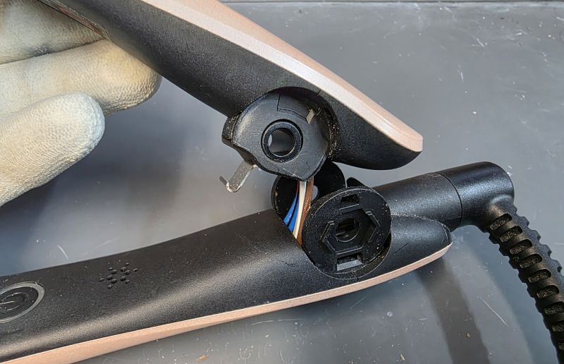
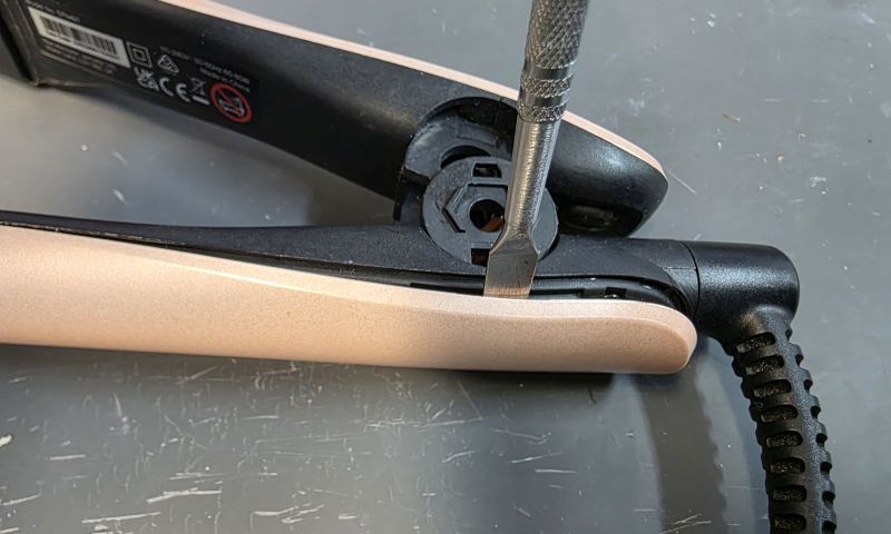
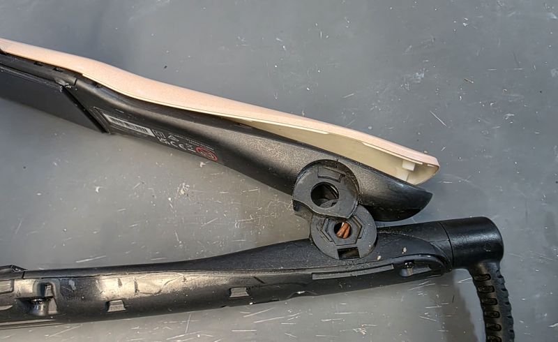
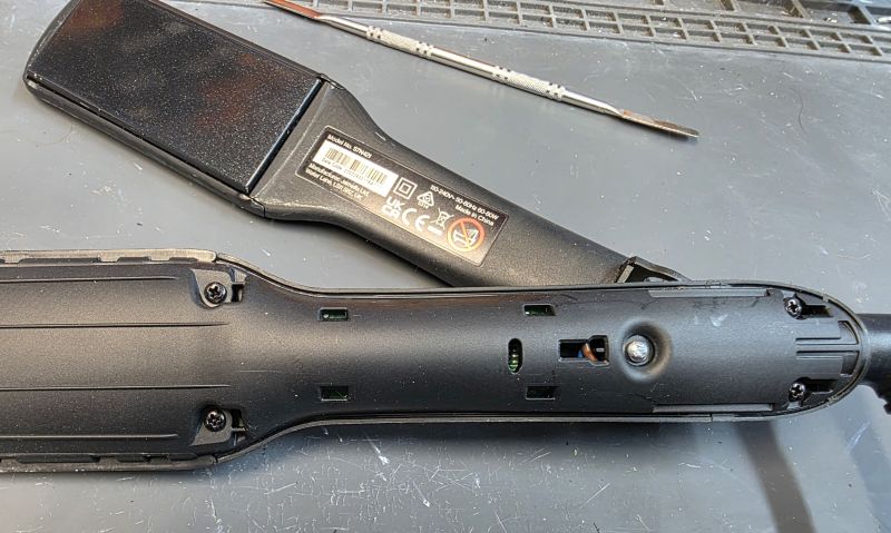
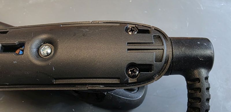
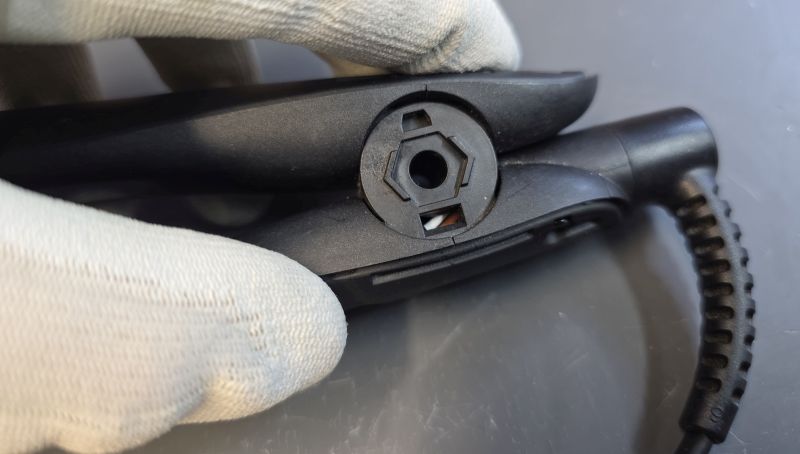
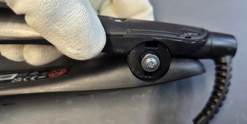
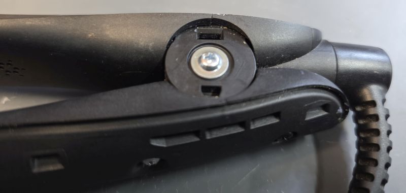
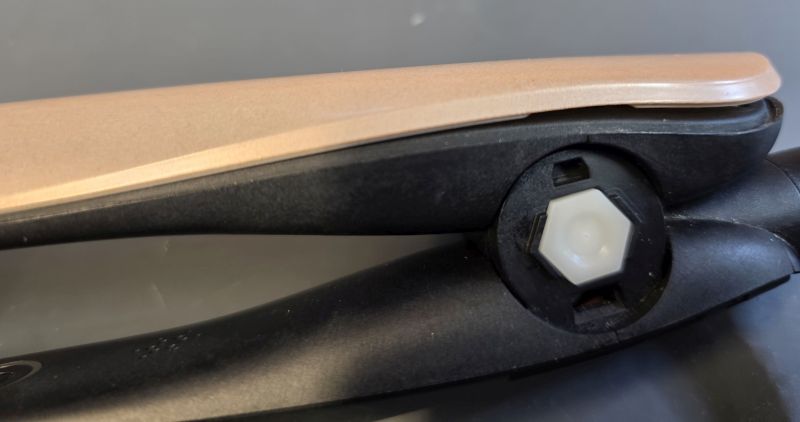
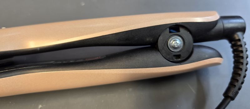
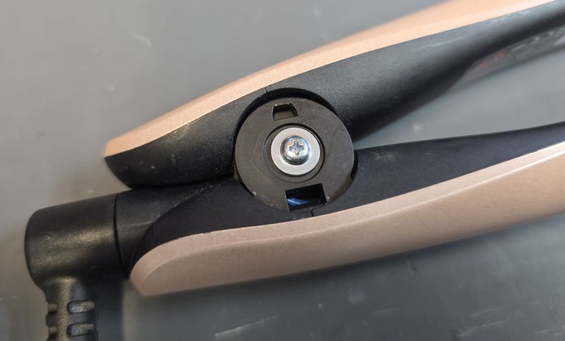
Separate the Arms
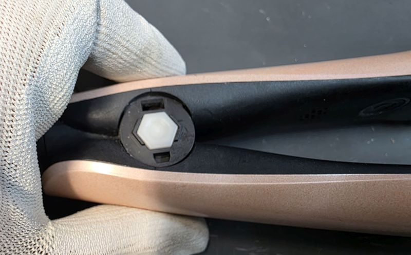
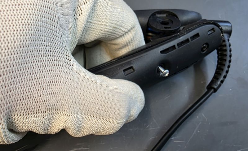
One side is blank.
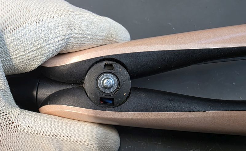
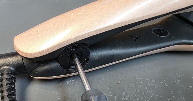
The other side has a screw head.
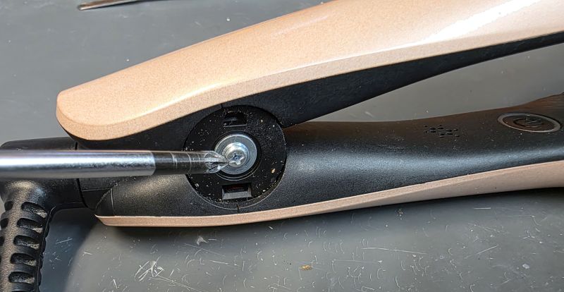
Unscrew and remove.
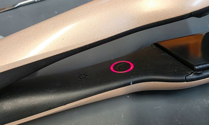
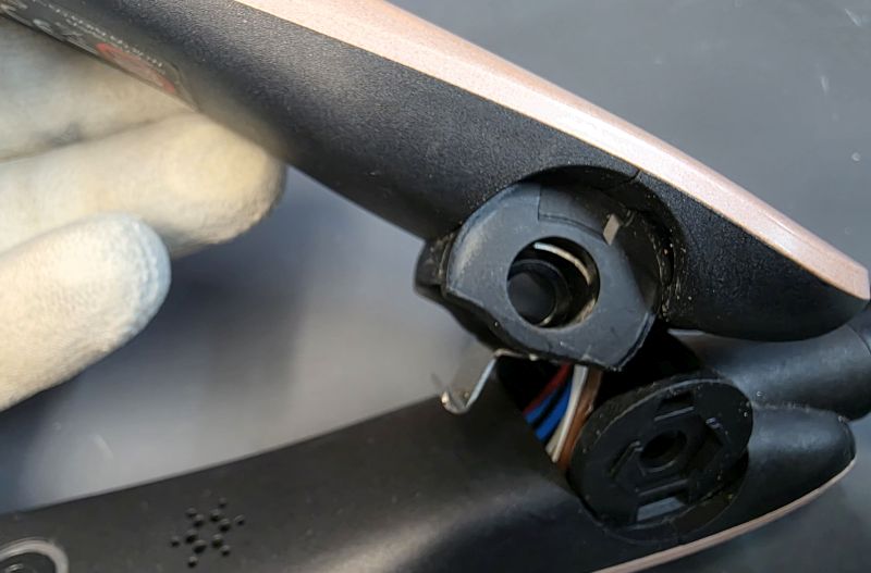
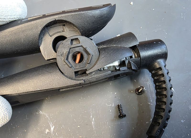
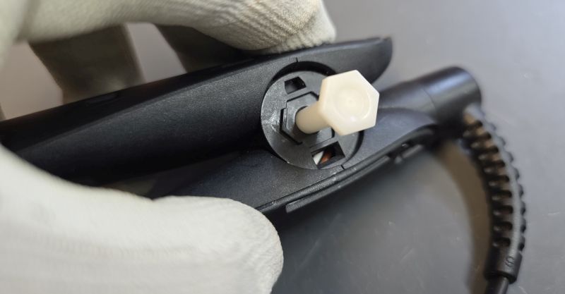
I mentioned earlier, virtually all faults will produce a flashing red LED and a bleep.
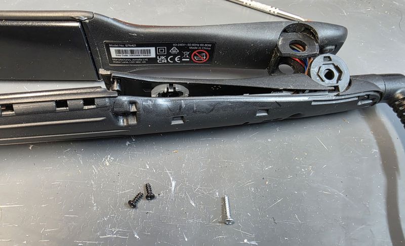
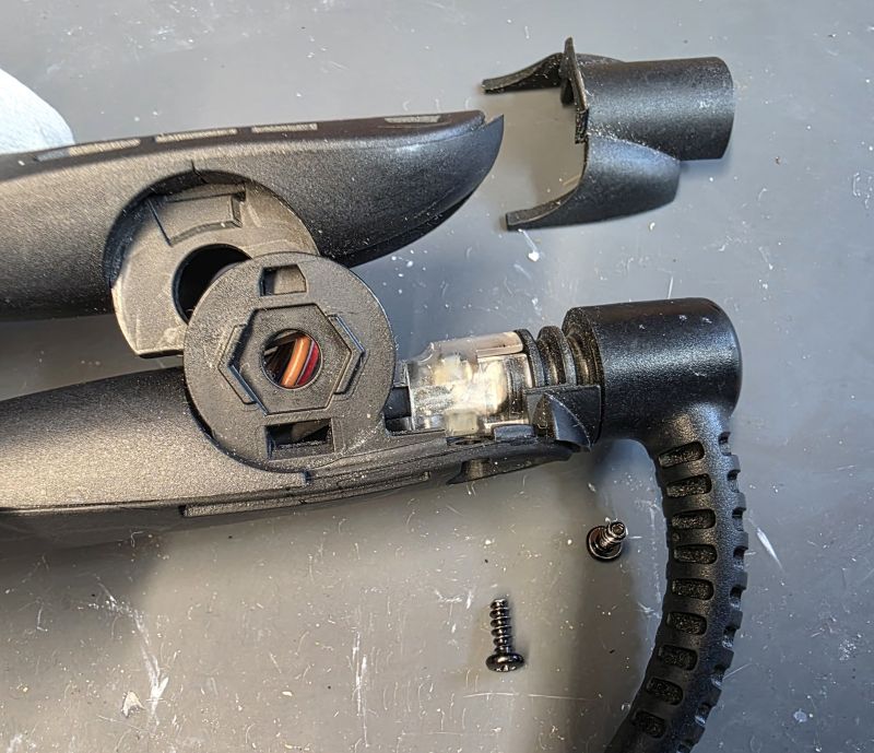
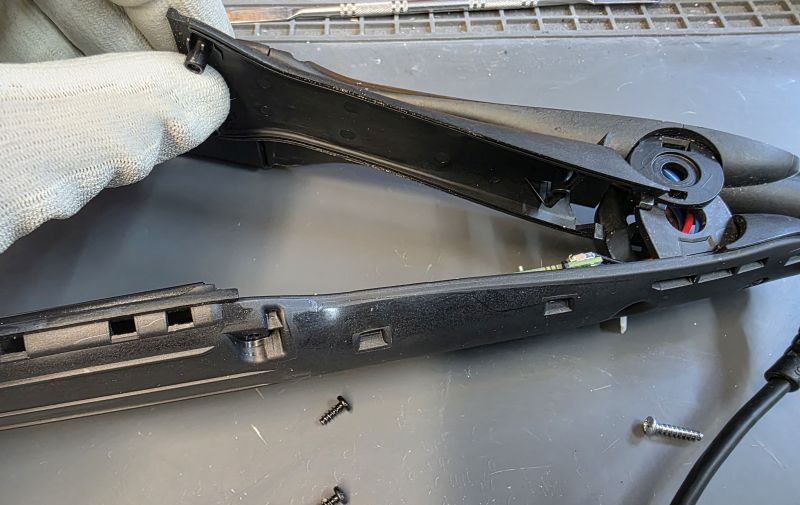
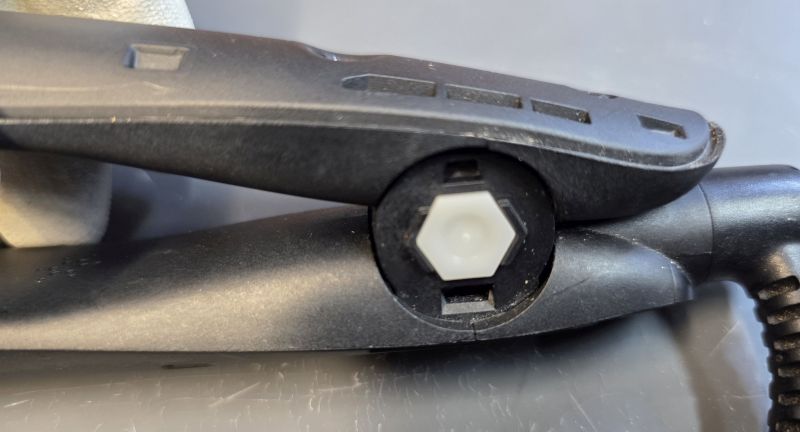
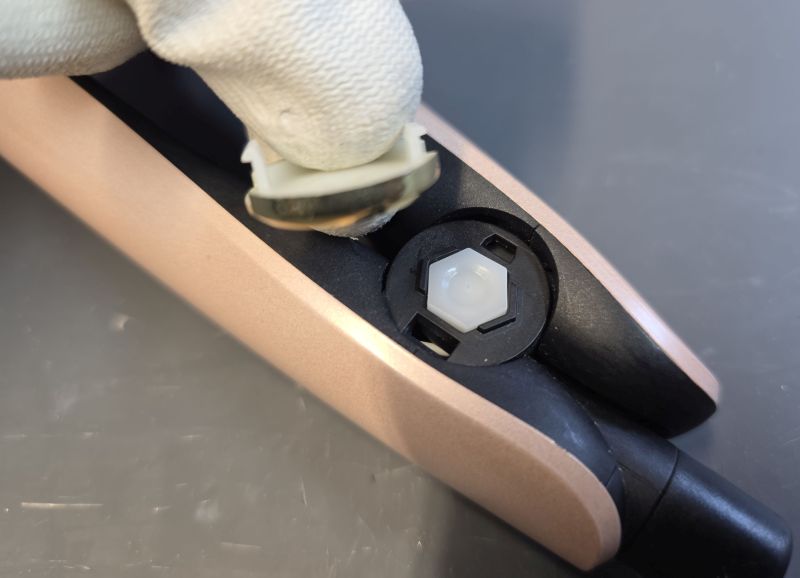
Press the white hinge pin out.
Separate the arms.
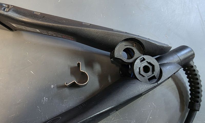
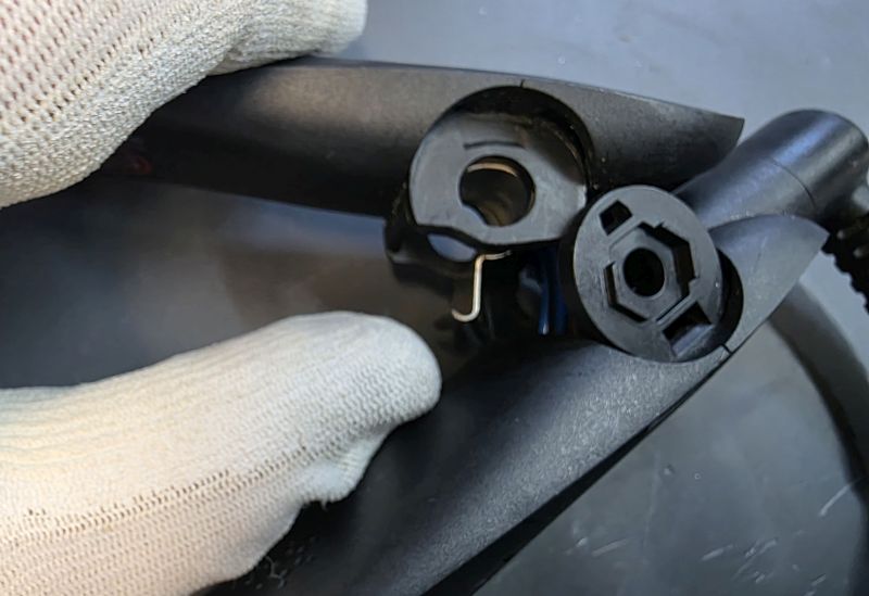
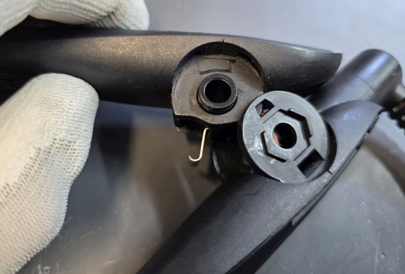
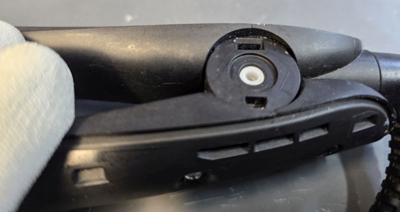
Push out the black or white hinge sleeve.
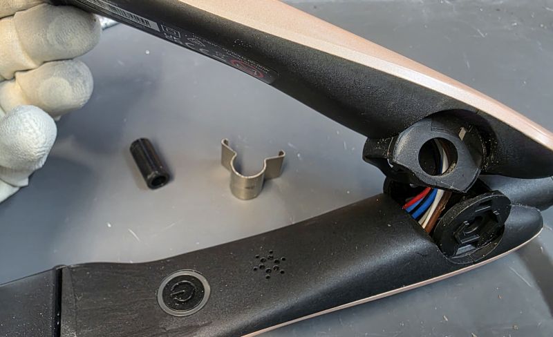
Remove the steel spring.
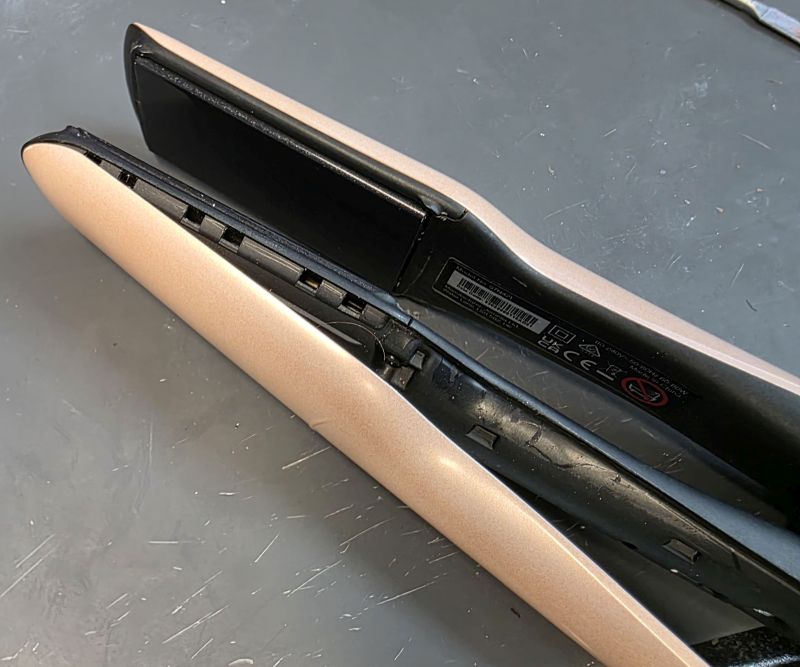
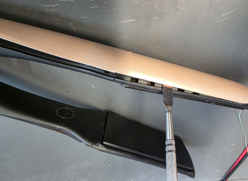
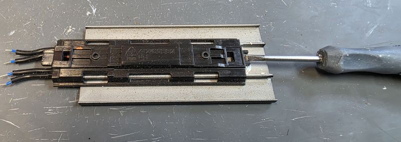
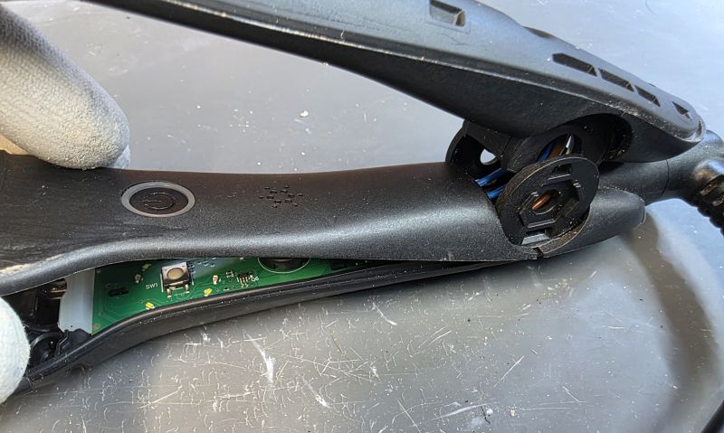
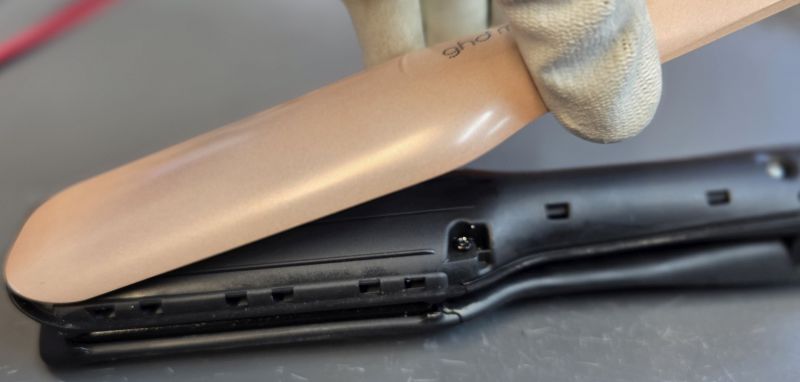
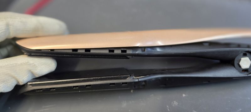
Remove Cosmetic Covers
With the same tool used earlier, carefully insert at the hinge area.
Gently pry open a small gap.
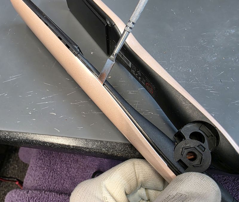
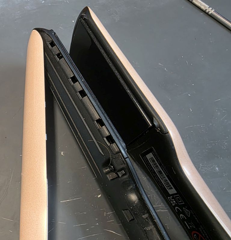
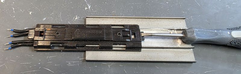
Continue down the side.
Repeat on the other side.
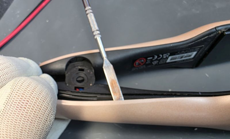
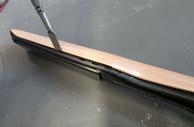
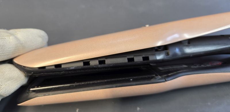
Ease up from the hinge end. There are clips at the heater plate end which you need to be careful not to break.
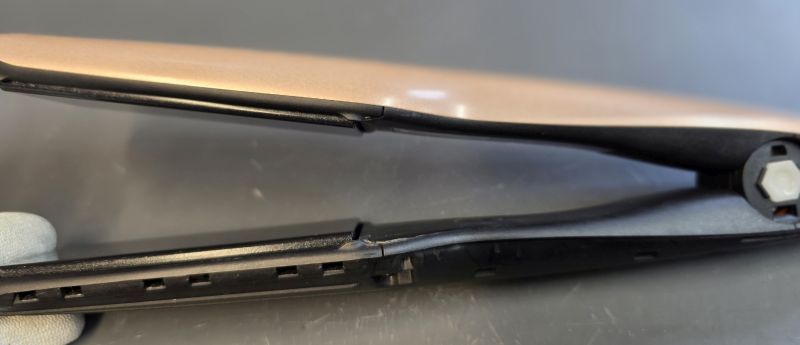
And then lift away.
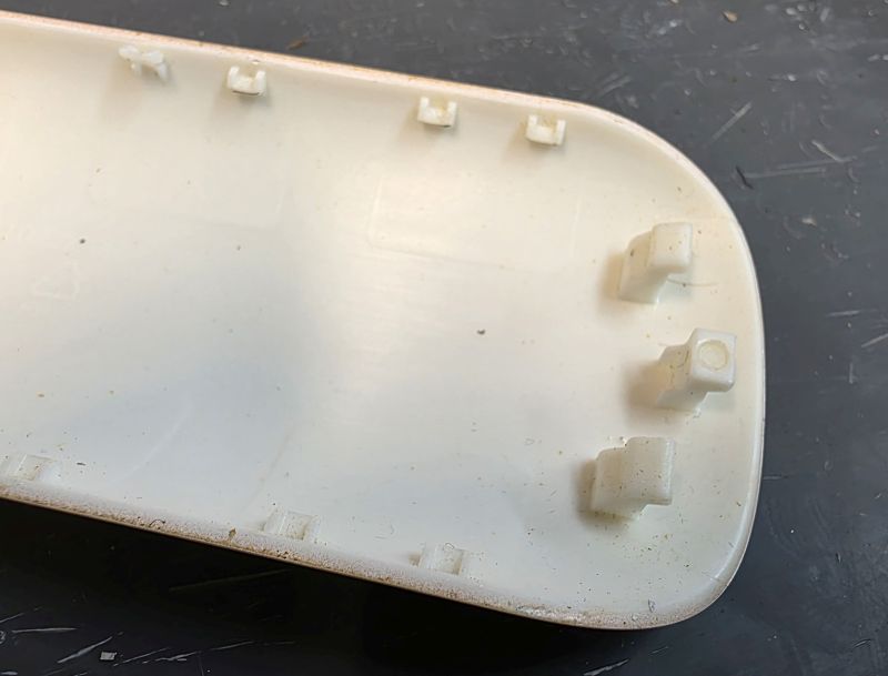
Make sure you do not damage the three lugs at the front of the arm cover!
The really small clips down the side will break, just a few normally but it is of no concern.
Repeat for the other side.
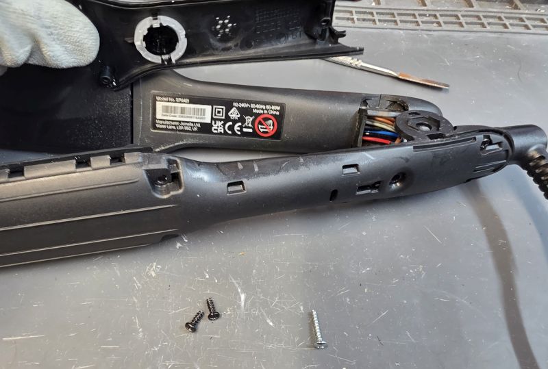
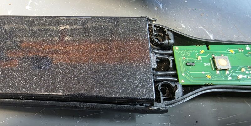
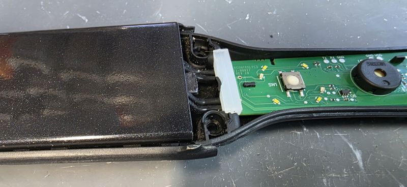
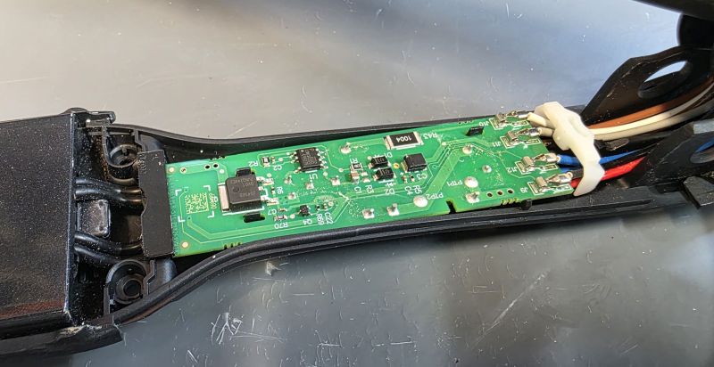
Open the casework
Remove the two black screws on the left and the single silver screw on the right.
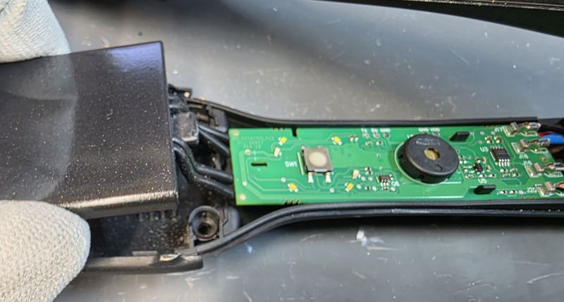
Lift the inner arm cover off.
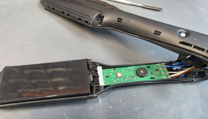
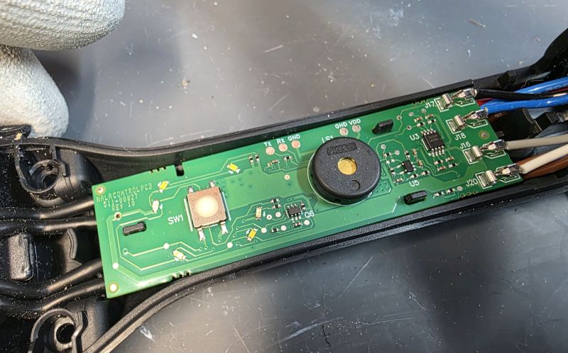
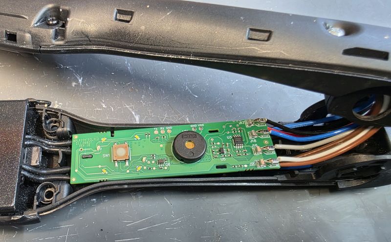
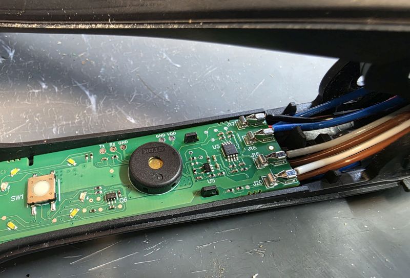
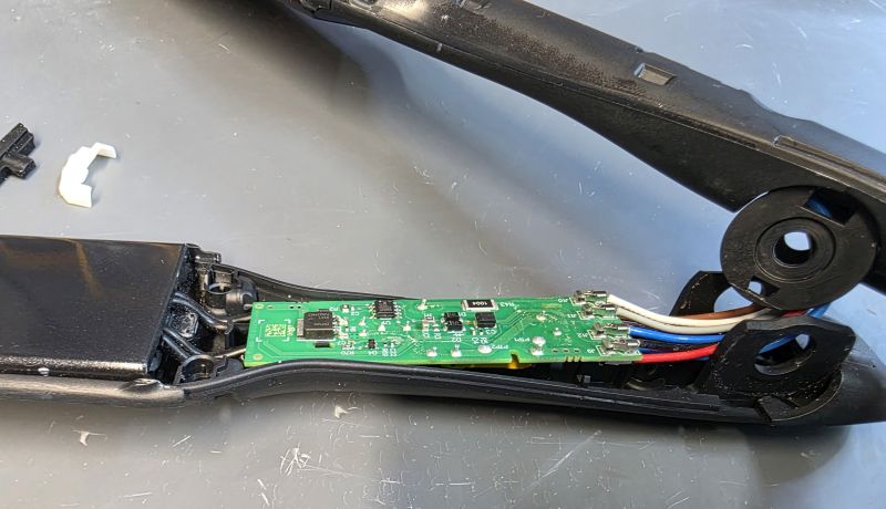
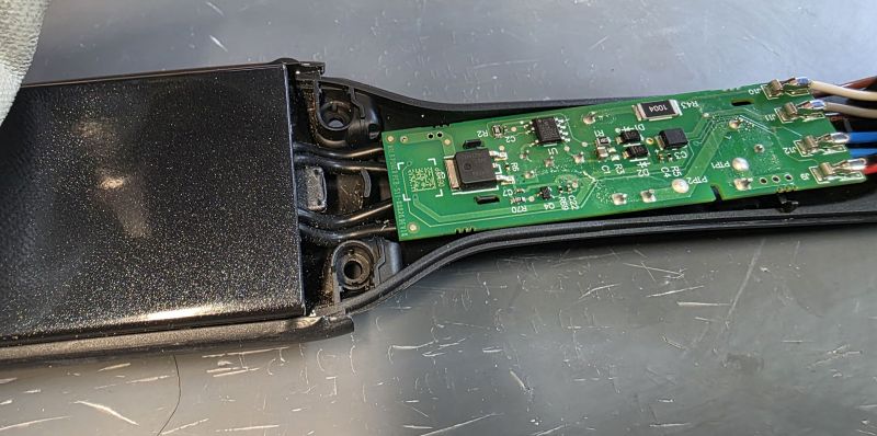
The switch side PCB is now exposed.
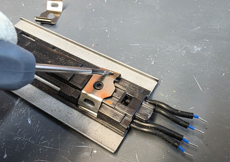
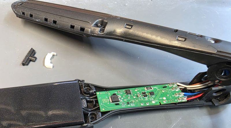
Remove the PCB
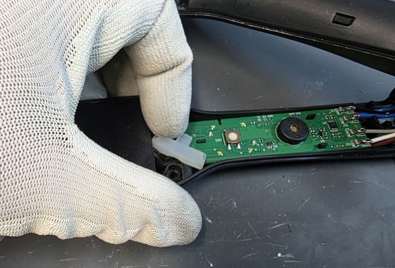
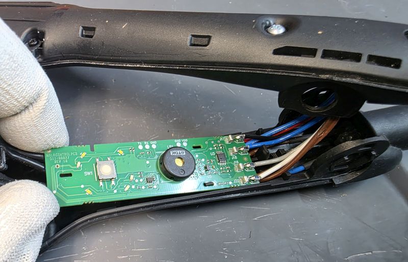
Remove the silicon rubber
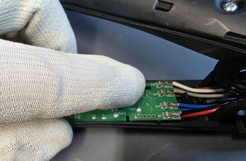
Note the three black tabs securing the PCB.
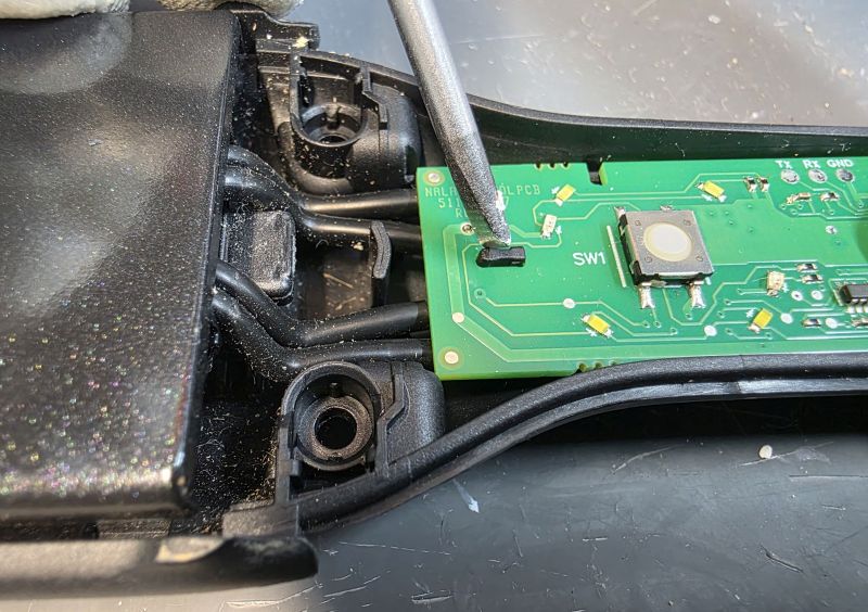
Gently press the tabs with a finger nail to release them enough to prise the PCB up.
Lift up at the front.
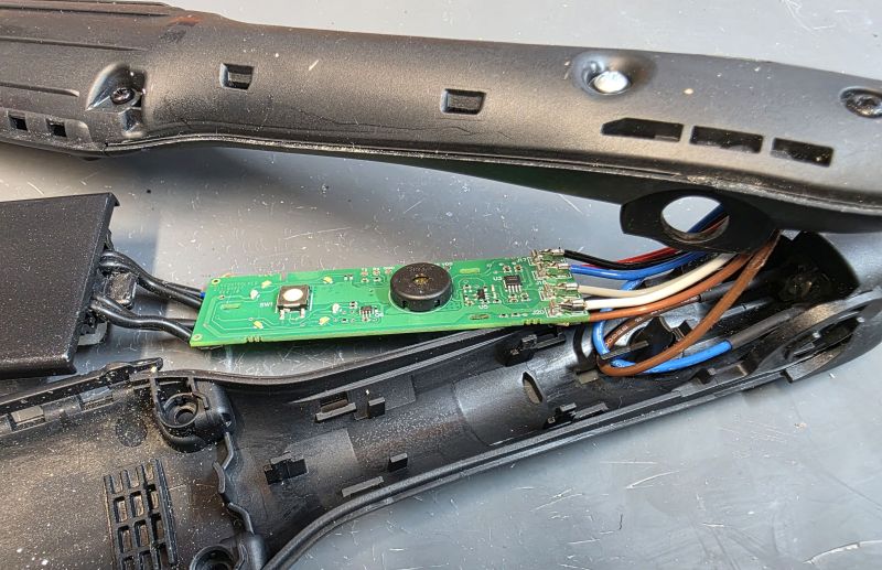
And then the rear. And lift away.
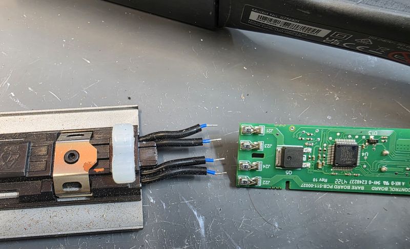
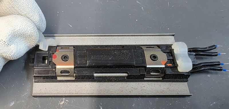
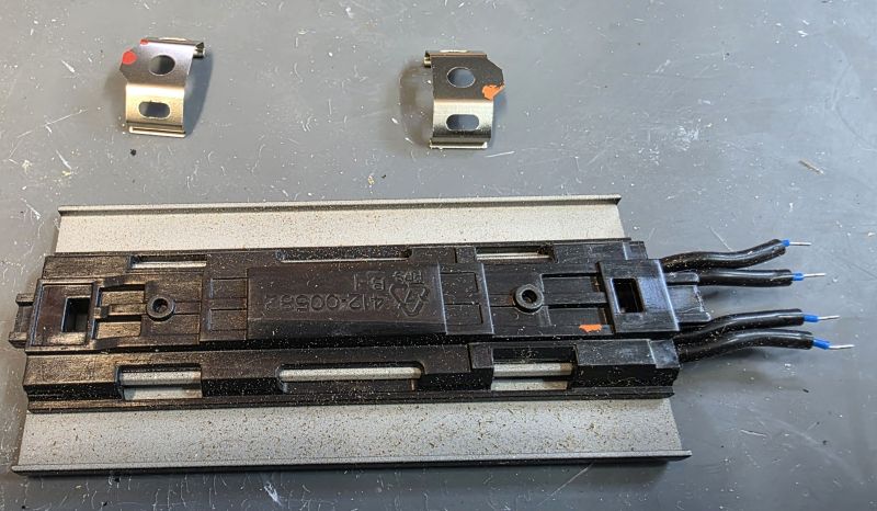
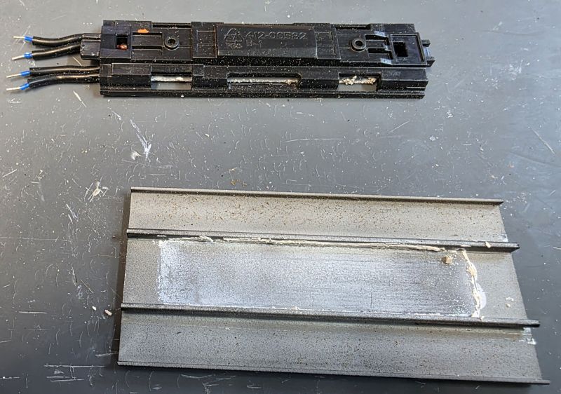
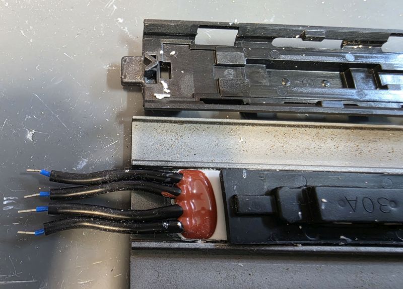
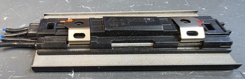
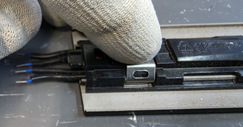
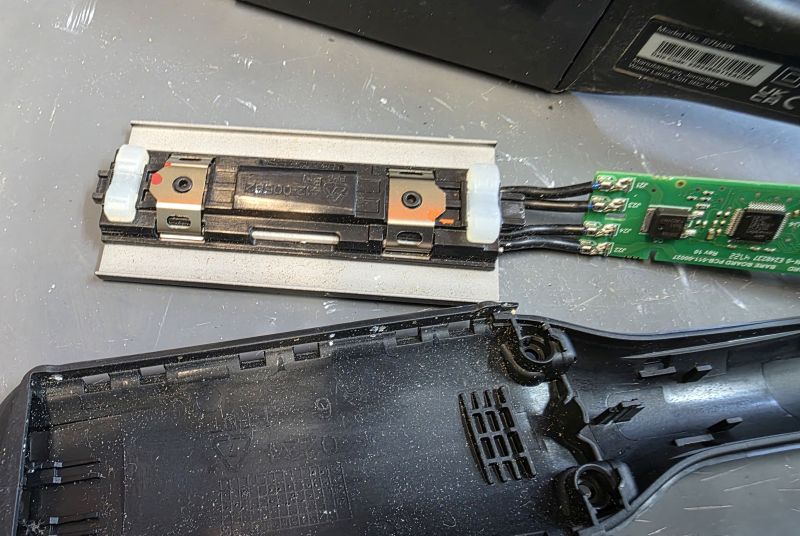
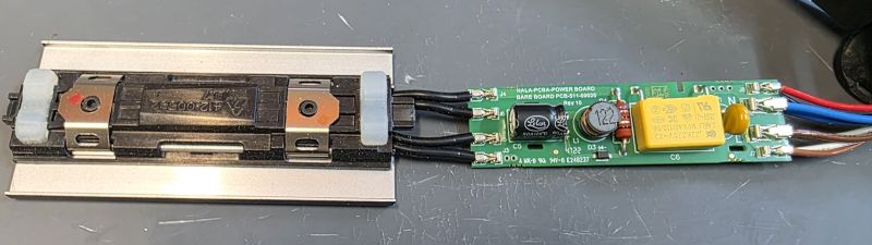
Dismantle Heater Plate
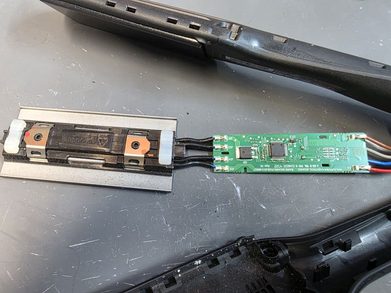
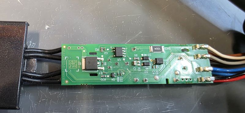
The reverse of the PCB, note the push fit element connectors.
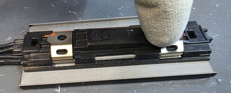
Separate the ceramic plate assembly.
Remove the silicon pieces. These rubber parts give the ceramic plates a bit of "float" so the plates can move over the hair smoothly.
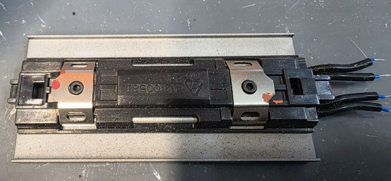
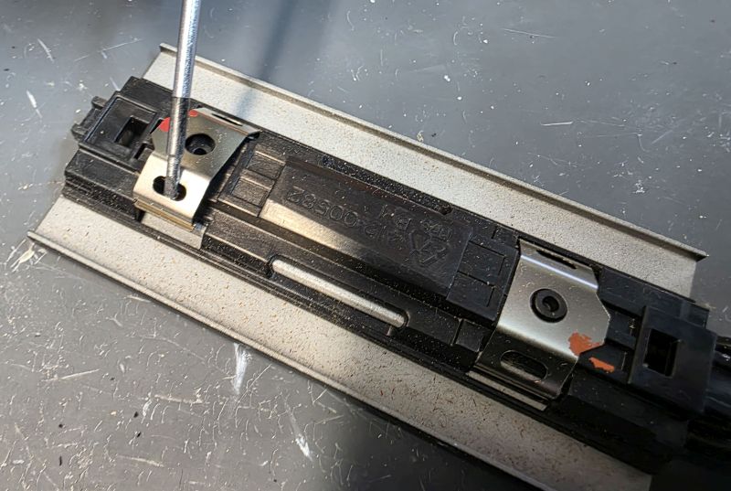
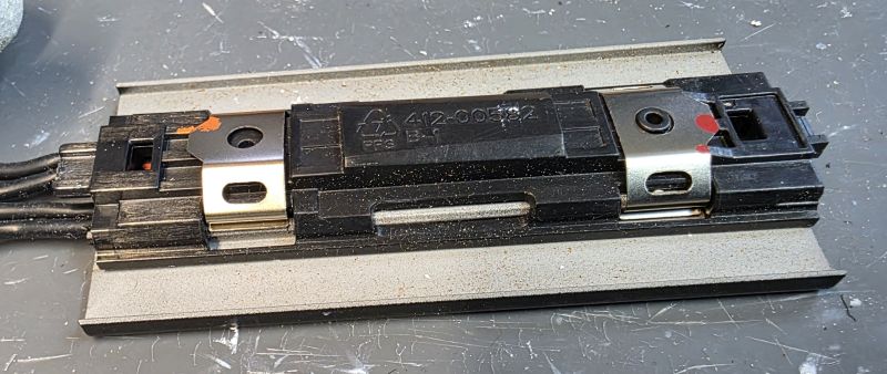
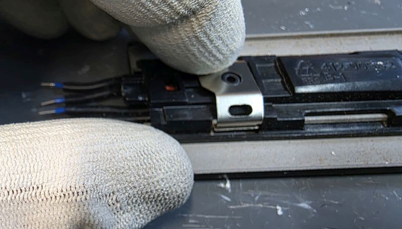
Remove the metal spring clips.
Slide the plastic mount and element out.
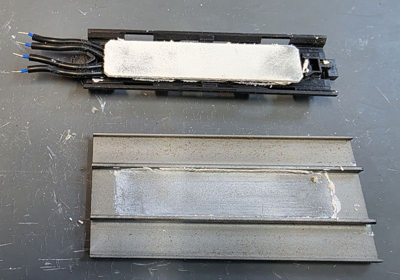
The white "gunk" is thermal paste which helps the heat get out of the heater element and into the metal of the ceramic coated plate.
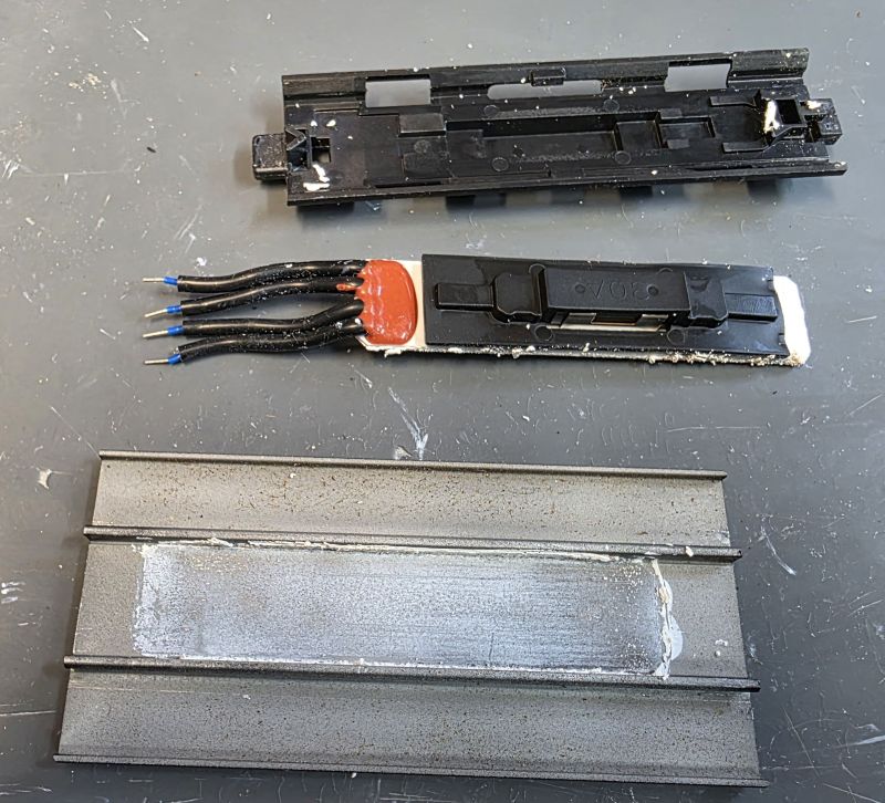
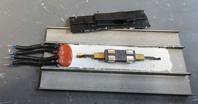
The thermal fuse contacts are spring loaded onto the back of the heater element and can often apear burnt. These must be cleaned and specialised high temperature solder used to solder them to the element to make a good, reliable connection. A preheater is required!
Reassemble Heater Plate
Note the plastic mount goes back this way.
Place over the element and silicon cover.
Press down hard.
The plastic mount will click in to place.
Replace the two metal clips.
Slip in one side and then press down on the other side.
Reconnect heater plate
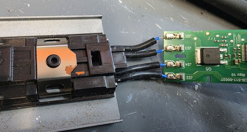
Another weak point is the push fit wire connectors. We solder them in place after using a Dremmel to roughen the wires to ensure a good reliable connection for the future.
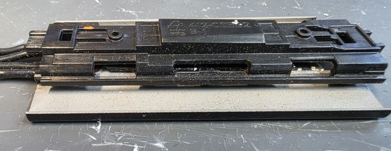
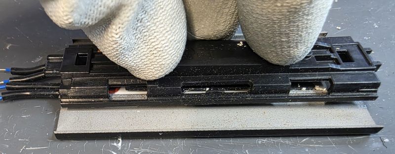
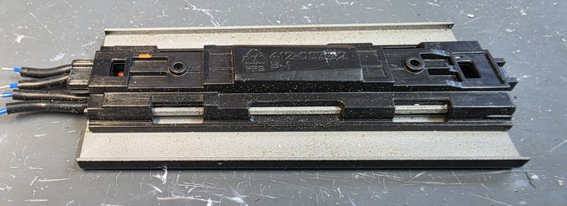
Refit Heater Plate
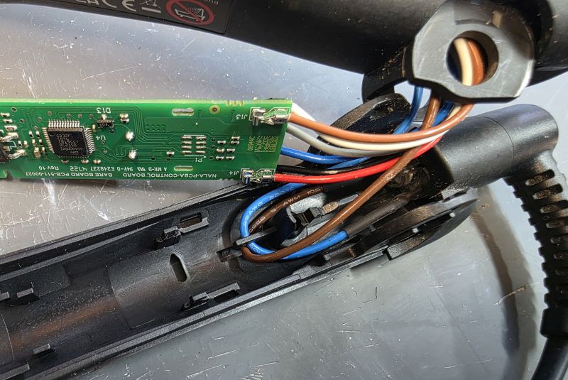
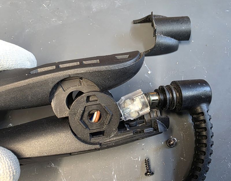
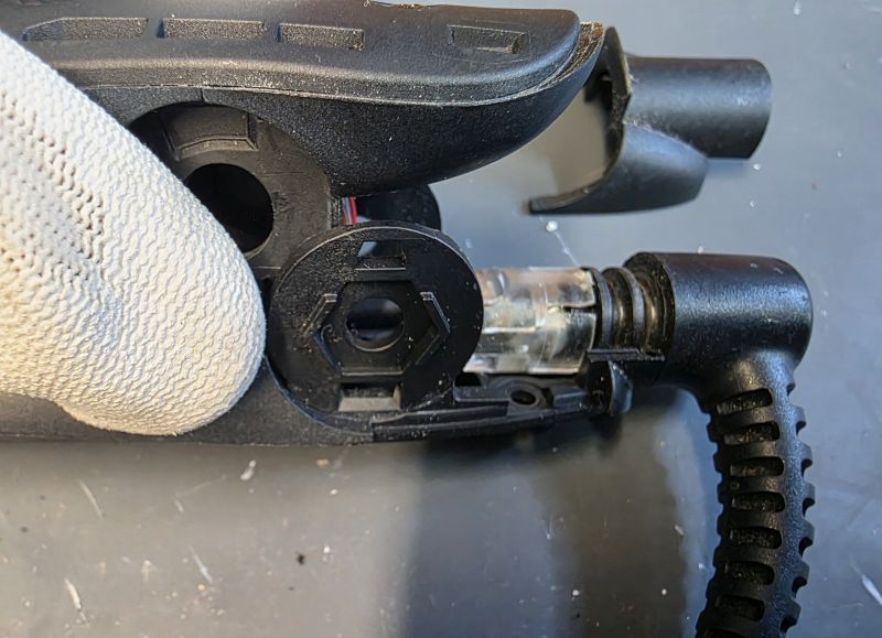
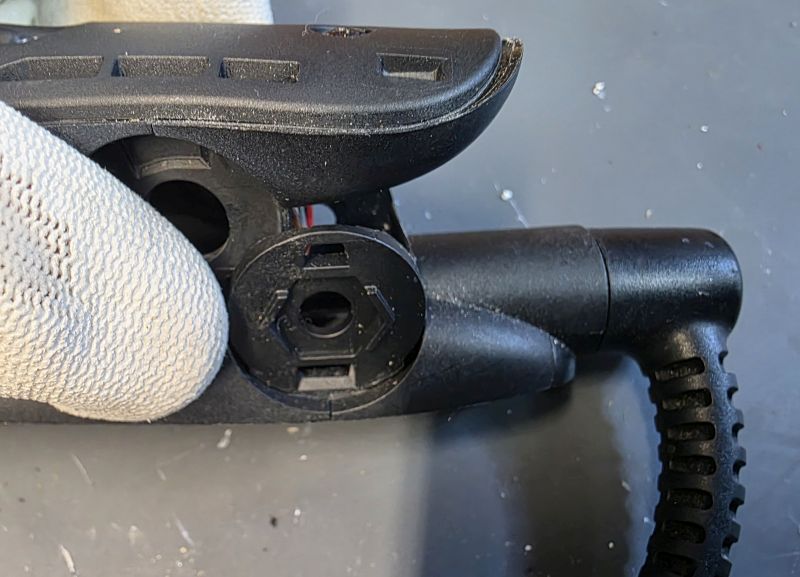
Note the orientation of the cable socket wires in the hinge area.
Don't forget the rubber bits on the back of the plate!
Reassemble. PCB in at the front.
Then the back.
Silicon rubber piece back in.
Cover back on.
Screws back in.
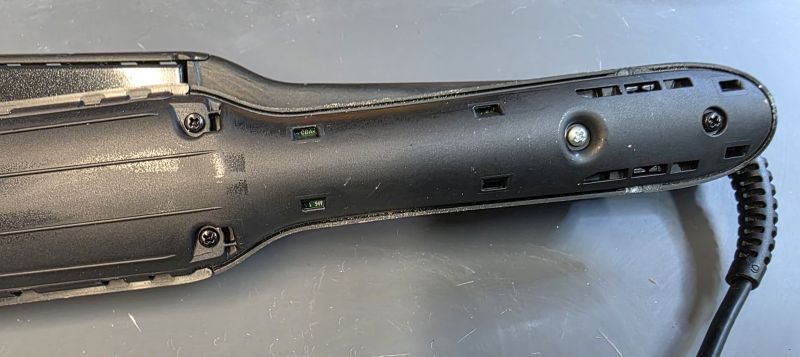
Cable replacement
Remove the two black screws on the right.
Lift off the cable cover.
Lift up and remove the cable.
Fit the replacement cable, available HERE
Cable cover back on and screws fitted.
Disassembling the Non Switch Side arm
On to the non switch side arm.
Screws removed and arm cover lifting away.
Arm cover removed.
Silicon and plastic pieces removed.
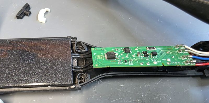
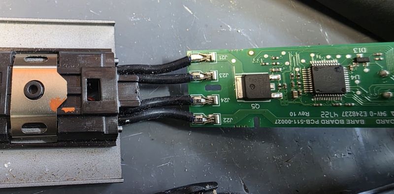
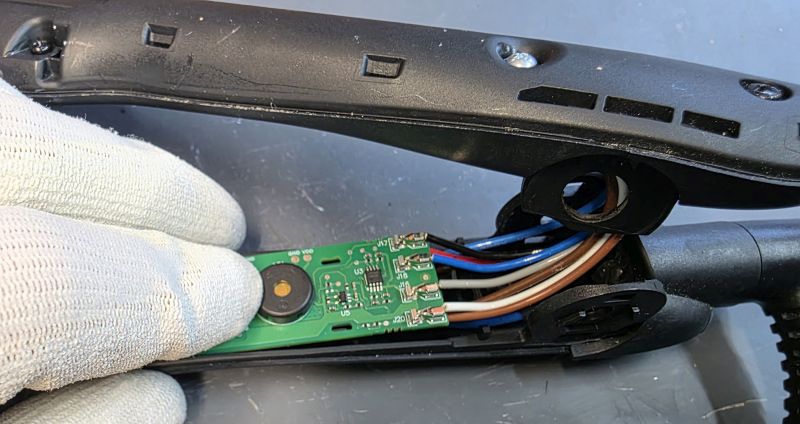
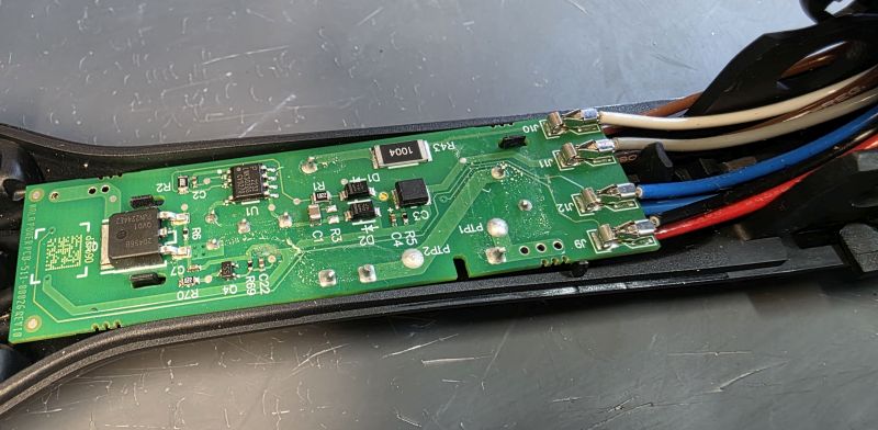
Remove the PCB as before.
This is the PCB that must be modified in all cases. We don't publish the details of the modification as that is our special information that we've spent a lot of time and energy working out for ourselves. Sorry! But this modification is always included as part of our repair service HERE.
Reassembling Non Switch Side Arm
Replace the PCB and silicon/plastic pieces.
Scews back in.
Reassemble Hinge
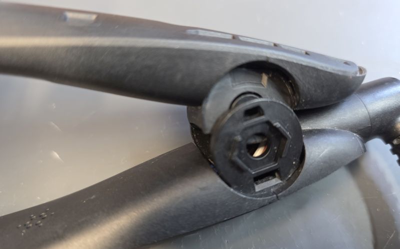
Hinge orientation.
Place in to the hinge area.
Slide in the black or white hinge sleeve.
Press the arms together.
Slide in the hinge pin.
Hold the pin in place.
Fit the screw.
Refit Cosmetic Covers
Replace arm cover. You must get alignment correct and start at the front.
Work your way down.
Click the last piece down.
Job done.
Same the other side.
If you see a gap anywhere along the arm covers, remove them, remove any broken plastic and then refit the arm covers.
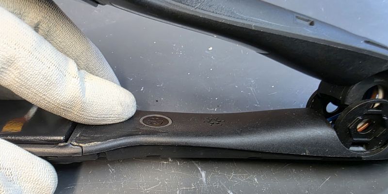
Replace Hinge Covers
Rplace the hinge covers.
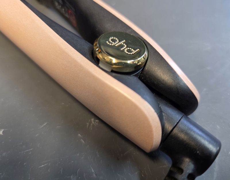
Note they have a short tab and a long tab to enforce the correct orientation for the GHD logo.
Press down.
Long tab goes in the hole that you can see the blue wire through!
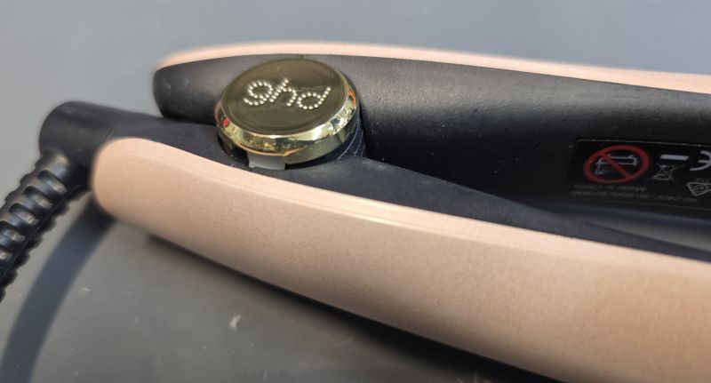
Press down.
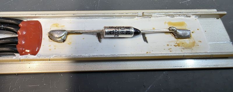
The thermal fuses shown
The top thermal fuse is the genuine GHD PEPI H1 thermal fuse and it must be replaced with another genuine part.
The middle thermal fuse is the lastest type fitted to irons produced recently and must be replaced with another genuine part.
The bottom thermal fuse is being sold and fitted by repairers who should know better. It is not suitable! It has not been approved or tested for use by GHD and should never be fitted! You'll see it is round, so has very little surface area contact with the heater element. This means it will not respond as quickly to an overheating issue which could cause a dangerous fire hazard.
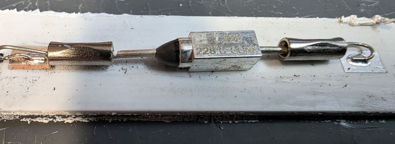
The following thermal fuse is not fitted by us and we would never recommend fitting a thermal fuse like this!
Hopefully this guide has been helpful! Don't forget we offer a quick and simple fixed price repair service for this model which is available on our online shop here.
We also sell all the spare parts you could need for the Gold and Max model here including cables, arms, circuit boards and lots more!
Short URL for this page: