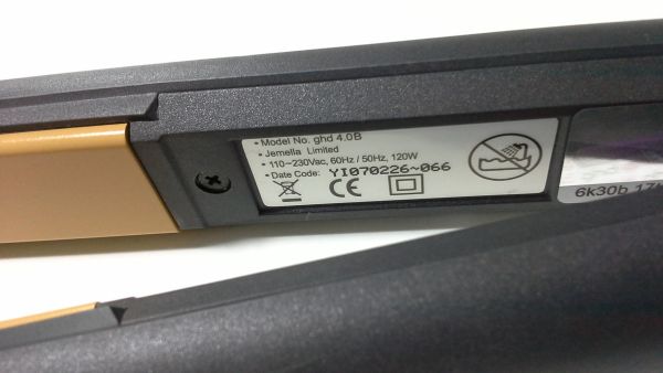
GHD 4.0B
This model is a MK4 pair of GHD straighteners in Black. For a guide to debugging this model please see the mk4 repair guide. They were also available in hot pink.
Normal operation is as follows:
- Switch on => Beep Once, LED on constantly
- Reach operating temperature => Beep twice, LED flashes.
If the temperature of the irons is below 5 degrees C then they will not work and the will emit a continuous beeping sound. To fix this, just bring them back up to normal temperature (gradually!) and then try again.
We stock lots of 4.0B spare parts in this section of the spares shop. This includes replacement cables (GHD 4.0B Cable) and the cable replacement method is described here.
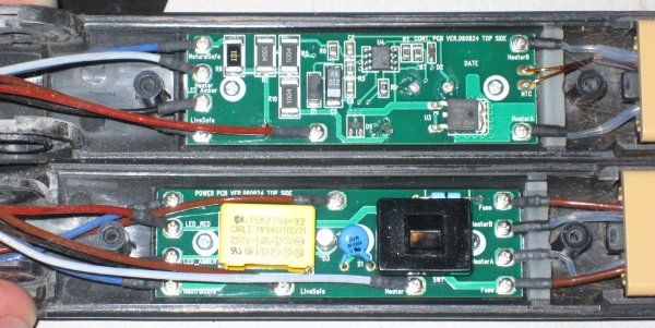
The heater elements are 70 Ohms each. When connected to the PCB they are in parallel, so you will measure 35 Ohms (if they are both working). See the heaters page for details of the replacement heater options available.
Most common fault with this model is R8 going open circuit in the electronics causing them to be completely dead (see the R8 Failure page).
Photos


Circuit Diagram
Mike Broom has kindly traced out and sent us the circuit diagram for the PCB found in GHD 4.0B's. It can be downloaded here - GHD 4.0B Circuit Diagram. There might be some "funnies" with this diagram, however it's reasonably close.
We also have a basic BOM in case it's of use to you:
|
Component Reference Designator
|
Component Type / Value
|
Comments
|
| R1 | 1 Meg Ohm Resistor | |
| R5 | 1 Meg Ohm Resistor | |
| R8 | 100 Ohm Resistor | |
| R10 | 1 Meg Ohm Resistor | |
| D1 | Diode | During correct operation it should have about 2.2V across |
| D9 | Zener Diode | During correct operation it should have about 2.15V across |
| C5 | 200uF 6V Capacitor | |
| C1 | 0.22uF 275AC Tenta Capacitor | |
| U3 | ST Triac | |
| U4 | Microchip 12F675 | Should be 4.5V between pins 1 & 8 |
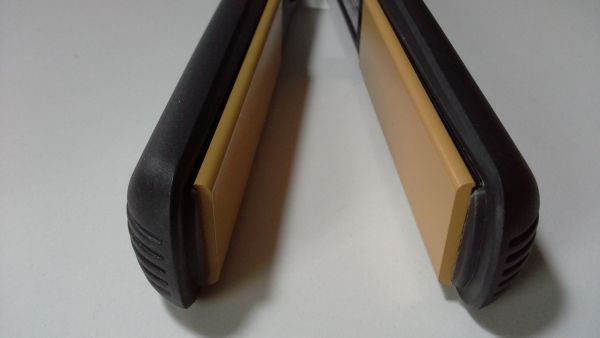
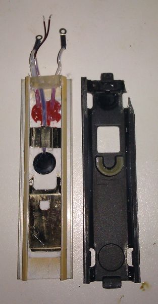
Heater with thermistor assembly
The thermistor side heater plate goes together as follows (ignoring the broken bit!):
FAQs
- Will my GHDs work in America?
- Will you fix my Fake GHDs?
- How do I debug my Mk4 GHDs?
- Help! My GHDs are broken! What shall I do?
- How do I replace a broken arm?
Short URL for this page: